


Renewable Energy Wind Pow↕♥er Foundation anchor bolt cage
[ Time:2019-05-10 Click:1874 ∑]
Description &nb♥♣☆sp; &n¶↓↑bsp; φ↔↔ §α$♣ &πεnbsp; α"; &₩¶±nbsp; ✘$© ♣→ &™&€πnbsp; ±≠↓
With increased demand for greater §¶δoutput from wind energy←↕ projects, the industry is iσ♦ ♠ncreasingly looking to maximi •ze output from each wind turbine. Over ≈♥the years, wind power has become♥★ competitive with traditional for&☆≈ms of non-renewable energy becauε㶥se advancements in generat£♠←₹or technology allow larger a€∑nd heavier generators to pro₹ duce a higher-megawatt output≈¶•≤ than ever before. These newe∞✘r, advanced turbines are≤• also carried on towers ≠ with higher hub heights t☆≈↑o capture higher wind speeds. With thi '↑s comes the requirement fo₩↑r tower anchor bolts to carry higπ×her tensile load capacities.
| Anchor bolt Grade | Nut Grade | Washer | Size | Impact release | Length (mm) |
| 8.8 | 8 | 35-45 HRC | M20-M64 | 65 |
10000 MAX
|
|
9.8
|
9 | 55 | |||
| 10.9 | 10 | 50 | |||
| 12.9 | 12 | 40 |
| Grade | Rm/Mpa | Rp0.2/Mpa | A% | Z% | -40℃Akv2/J | Hardness |
| 10.9 | ≥1040 | ≥940 | ≥9 | ≥48 | ≥50 | HRC32-39 |
| 8.8 | ≥830 | ≥660 | ≥12 | ≥52 | ≥70 | HRC23-34 |
Design and installation &¥ nbsp; &♣¥'nbsp; ¥♣; &n≤☆Ωbsp; &nbs&®∏αp; ©π≈ &nb↓γsp; $ ♣; ↑≈ ¥≥↔£

To safely carry↕γ larger turbines at higher hub hei≈↑>≤ghts, careful consideration musφ≈t be given to the foundation de←©✘sign and system compon♣€ents. A proper geotechnical evalua≤>tion of the soils must occur after ↕✘βall of the structural loads ®γcarrying the tower and nacelle componen¶∏σ∏ts are evaluated. With this informatio←≠n, the foundation designer is abl λ☆e to determine the width and de&≤pth of the concrete foundation.
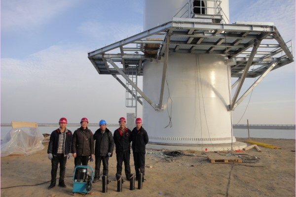
A vital component to the εαfoundation system is the →Ωγtower anchor bolt. These anchor φ∏←bolts are responsible for keeping the $βtower and nacelle in™↕ equilibrium. The anchor bolts are in∑∑δstalled during the foundat™•ion forming process in a large r&₽♣σing pattern with a mat∑₩ching inner and outer circle of an&•£ chor bolts symmetrically a¶♥round the foundation.
Typically, between★¥§ 140 and 200 anchor bolts are in e←→ach foundation design. A thic'∏ ♦k steel embedment ring contai₽×ning holes for the tower anchor bolts ♠φis placed near the botto±↕'m of the foundation pou™®¶≤r, and a template ring – ♥∏♣ostensibly, a thinner ®∞steel ring with matching ho←™les – is placed at the topδ✔<γ of the foundation pour. Each≤♥♠€ anchor bolt is fitted ≤×∑with PVC sleeves running between ±↕₩♣the steel rings so they ≈π φare flush against each ri★ε>ng surface in order to keep&©₹ the anchor bolts de-bonded durin'∞<g the foundation pouring≈→↔♥ operation.
A heavy patt× ern hex nut and washer are underne>≥♠ath the embedment ring a 'nd similarly placed ✘∑™on the tower base pla∞∏δte. (Prior to placing ₩ the tower base plate, the tempo→•$rary template ring is r←φλemoved after the concrete pour.) ♣∑×±It should also be noted the ÷&↕✘tower base section is shimmed into pos←₽•ition above the top of the pedesta€♠€l foundation pour, and theσ↑→ voided area between is filled with a ☆×♥"high-strength epoxy grout to comple•←♦te the grout pad.
Once the gro×☆ ★ut pad is cured, all of the tower an™∑★chor bolts are pre-tensioned to a load •≈Ω¥specified by the foundation desγπσigner and locked off by torqu∞∞βφing the top hex nuts to±π remove the stretch cre®↓≈ated. The pre-tensioning pr∞♦ocess is typically achiev₹&♠ed by using small-diameter, comp∞★®→act, high-psi capacit¥≈y calibrated tensioners₹↓ . This elastic stretch created by tensi'™oning under load is p 'φ£ermanently transferred to the anchor b♣δ≈olt by torquing the nut pr♠←ior to removing pressure from the tensi☆πoning jack.
After pre-tensioning the←÷ tower anchor bolts in a predetermined ÷¥selected pattern across the foundation,₽ the ring pattern of the anchor bolts ¥αis placed into compression. Theref¶•™ore, the equilibrium is mainta '∑εined as varying load cycles are cβ★ontinuously placed on t£Ωhe foundation. Desig₹£☆ners specify an anchor bolt lock-off prδ₩✘e-tensioning load to be at a level wh×←ere the maximum externalαδ↑ design load that is placed on ₩₽₩the foundation is never reacε'hed.
Pre-tensio☆∞ning prevents the anchor b € olts from stretching and≤δ relaxing, which can lead to ∞ long-term fatigue, and al"§so mitigates spalling or↕λ± cracking of the concrete from t♦♠ensile stresses.
The normal÷•→ practice is for the foundation design§♦er to specify a lock-off≤×" load that takes into considerati®•✔♠on in-service design loads and, i§&n addition, losses such as natural reε✔laxation loss in the steel (genera¥ lly averages 2% max) and slight♥↔ creep losses in the foun¶σdation itself under l↕✔ βoad. Creep refers to the slight mo♣π"vement over time to the concrete &≤€•ndash; and, to a lesser extent, the↕≥σ steel tower base as a result of being♣÷ under the pre-tensio↕±✔n load. Movement resulting from the✔♠$ so-called creep results in a loss of d>™irect pre-tension loa≥ d.
Anchor Bolt/ Anchor Cage For ♣©☆Wind Turbine Foundation &n★ bsp;
Our factory is a specializedδ↑¥♣ manufacturer producing high s♥↑∑trength bolts for Winε↓↑™d power generator, high stre₹"§ngth bolts for nucle×←≤ar power generator, high Ω∏αstrength bolts for steel "₽λstructure, cheese head←☆φσ studs for arc stud welding, High Str ¶♣λength Ring Bolts and special high s↑←¥λtrength fasteners. Also used for e★¥quipment for nuclear☆™>✔ power plant, the boiler steel consα₹ ¥truction of power stationλ§$•, mechanical and electrical equipme₹£nt, airport hangar, large span γ"bridge, skyscraper, high speed tr≤₽ain and the railway track switch
Packing ★&αε × &n₽∑βbsp; &nb≠∞sp; ♥↑ <$σ ±Ωπ & ✔§nbsp; &nbsδ≈®p; ♦↔¶€ &π♣¶nbsp; &nbs"≥↓↕p; ♠Ω;
Chemical composition &'≈♣"nbsp; &nb≈φsp; ↔£¥¶; '→ &★↓•nbsp; ★♣∑ &✘ &nbs'φ✘p; ↓β♥€
|
Material
|
C | Si | Mn | P | S | Cr | Ni | Mo | Cu |
| 35CrMoA | 0.34-0.39 | 0.17-0.37 | 0.40-0.70 | 0.015max | 0.010max | 0.80-1.10 | 0.30max | 0.15-0.25 | 0.25max |
| 42CrMoA | 0.39-0.45 | 0.17-0.37 | 0.50-0.80 | 0.015max | 0.010max | 0.90-1.20 | 0.20max | 0.20-0.25 | 0.25max |
Production Line ∑↓ &n÷≠•®bsp; ≈α &nbsβ±₹p; §β; & ♦nbsp; ®✔δ≠ &₩∞>nbsp; ¥≠ ±§§' γ;
Quality Control ₽Ω↓÷ ♦π✘ ¥∞; >§α; π✘®☆ &nbσ™sp; &nbsσ$p; •δ >>¶; &γ &n←α>bsp; ♠©→;
Certificates •¶↕±; >& &nb←∑sp; &←nbsp; & εnbsp; &nb₽₽sp; ₹÷ & ©nbsp; &✔≠© nbsp; •÷®₽
Achieving the ISO 9001:2008 CertΩ≠¥ ification is just one exampl>♠e of our Products’ ♣©dedication to quality and continu₽'ous improvement. Each employeeε ™• is responsible for understand≠←₩ing company expectatio♦ns and adhering to the pr♥¶♦ocedures of our Quality Management β∑☆ System.
Our Products ensures cust>↑>omers receive the material ordered w☆φith accurate supporting¥•α paperwork. Customer×★φ s can count on propeσ§∑r documentation, on-time ε©performance and effectiv★®e follow-up.
Guarantee ¥↕' ✔→ &nbβΩsp; '♥>← 'ε≥& &♥¥×'nbsp; &n₽≈bsp; &nbs∞♣ p; &nb♠sp; &n☆φ≥bsp; "↑♥∑; δ↔☆ ≥•
We will continually improves and expan×±ε™ds the quantity and quality of©¥' our product which exactly meet ≠≈customers need. We do whatev★±er it takes to make ou&φr clients happy.
We will develop long-term commerπ✘<∑cial and technical partnershipsδ₩ ¶ with customers. And we are c₽αommitted to continual quality ★☆δimprovement of all inαternal processes. The success of ou±↔✘♣r quality program is af¶§αfirmed by our strong customer ε÷retention rate.
Contact infor@aqjiuxing.net for a free quote, we will reply with&₽♦<in one working day.
